Electrolysis
Different types of corrosion:
Corrosion is one of the biggest enemies of a yachtsman. There is a lot of misunderstanding about corrosion. One often mistakes the corrosion taking place under water for the corrosion taking place above deck.
It’s very important to identify two types of corrosion:
- Chemical corrosion or dry corrosion. This type of corrosion takes place when metals are attacked by certain elements or combinations of elements. This type of corrosion takes place above deck. A well know type of this corrosion is rusty iron. The protection against this type of corrosion is achieved by surface treatment.
- Electrochemical corrosion or wet corrosion. This type of corrosion arises from the creation of an electrical element in a watery environment. This electrical element is build by two different metals with an electrolyte in between. The best example for such an element is a battery as used in every yacht or car. This electrochemical corrosion is also known as electrolysis or galvanic corrosion. As this corrosion is the biggest danger for all underwater metals we will go into depth how avoid this.
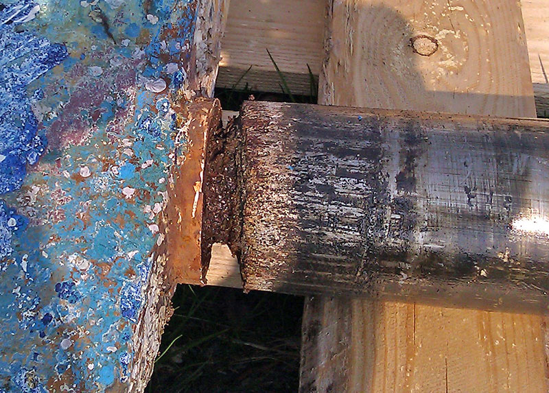
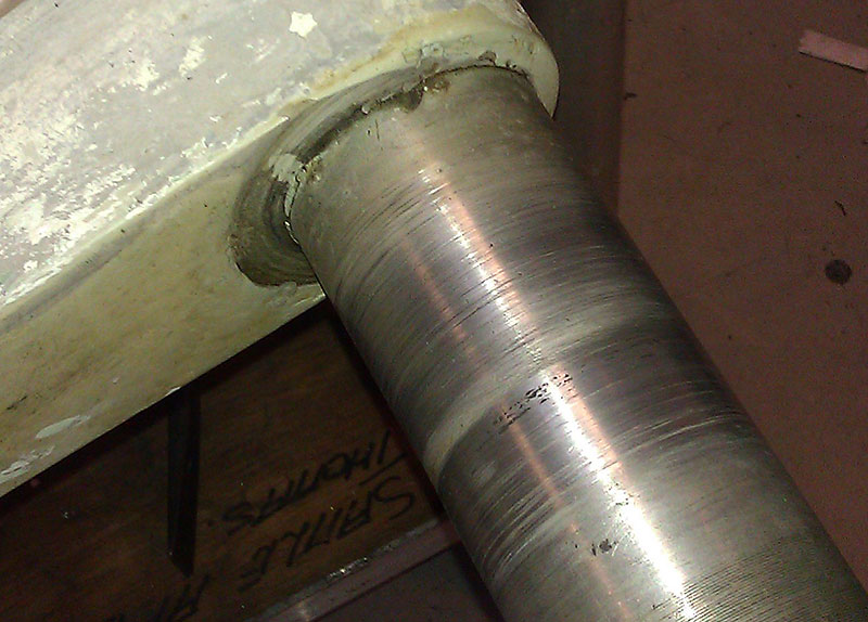
The principle of electrolysis:
The principle of electrolysis is based on the fact that when a metal is put into water it will create a non neutral voltage. On the surface a very small quantity of positive charged metal ions will break out leaving the negative charge in the form of electrodes behind in the metal. The reaction is (Me=metal) Me -> Mez+ + z e. The metal will be negatively charged. As long as this metal is not connected to another object with a different charge, nothing will happen and a balance will have been reached.
The reaction as described above is not enough for electrolysis to arise. The problem starts because all existing metals have a different charge when put underwater. Some positive, some negative. The absolute charge varies and increases when the temperature rises, the amount of salt in the water is higher and if more oxygen is present in the water. The absolute worst place for electrolysis is the Mediterranean as all factors are on it’s worst.
The phenomena described above is still not enough for electrolysis to arise. Only when the two different metals are electrically connected, electrolysis can start. One metal (the one with the most negative charge) will act as anode and sacrifice itself. The other metal with act as cathode. As the anode is electrically connected to the positively charged cathode, it can’t reach it’s natural negatively charged balance as described above. But it will constantly try to reach it. To get a more negative charge, the metal will split constantly into positively charged metal ions breaking out of the surface and leaving behind the negatively charged electrons. The electrons will be transported through the wire connection the two metals to the more positive charged cathode, and the whole process will start over again. It will only end when the complete anode is dissolved.
Electrolysis on GRP and composite yachts:
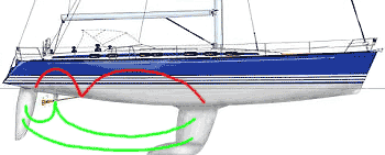 Lets now project this theoretical phenomena to your sailing yacht. First we have to determine which metal will start acting as anode. Following list is a sum up of metals in order of electro negativity, starting with the most negatively charged metal: Magnesium, Zinc, Aluminium, Steel and Iron, cast Iron, Stainless Steel (active) , Lead, Brass, Copper, Bronze, Stainless Steel (passive), Carbon. (One can make Stainless Steel passive by chemical treatment after machining). Second, the hull material is important. Lets start with composite hulls.
Typical rudder stock metals are aluminium and (active) stainless steel. Typical propeller shaft metal is (passive) stainless steel. Typical propeller metal is bronze. Typical keel material is lead or cast iron or a combination of both. (The propeller shaft can be made out of passive stainless steel as the geometry is often very simple, no welding will have to be done and can be ordered as passive stainless steel).
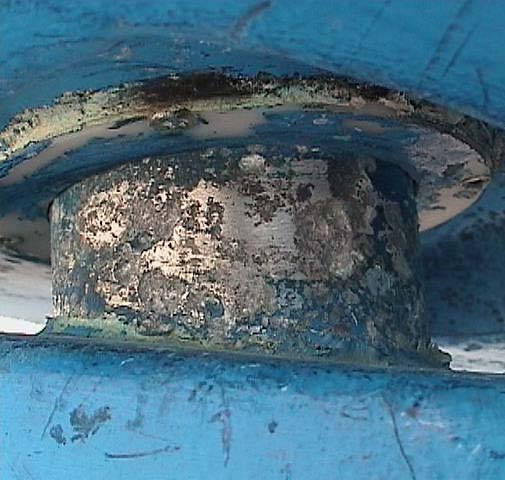
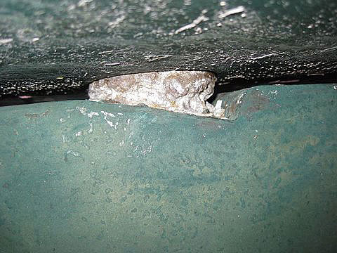
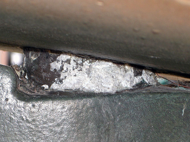
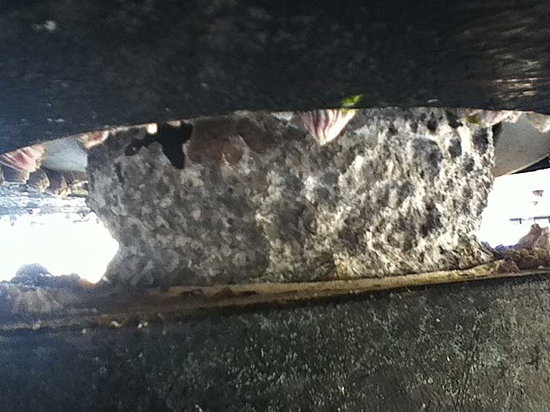
Lets take a yacht with an aluminium rudder shaft, standard propeller drive system and a cast iron keel. Some boat builders choose to connect all three parts with a copper wire (see red line in illustration). They protect the complete system with a zinc anode on the propeller or propeller shaft. The zinc anode has the lowest electro negativity and will act as anode. The propeller shaft, made of passive stainless steel, will act as cathode. As long as the zinc anode is present, it will all go well. Problems will arise when the zinc anode either is completely dissolved or falls off. The new anode will be the aluminium rudder shaft, which will start to sacrifice itself. Even if one had chosen to use a stainless steel (active) rudder shaft, the same would happen: The rudder shaft will start to dissolve in the water. A typical example is a Scandinavian boat owner, having sailed years without any problems, now take’s his yacht to the Mediterranean and is confronted after one year in the water with the fact that the zinc anode has been completely dissolved in the water and his rudder shaft shows signs of electrolysis. The extreme salty and warm environment highly increases the electro potential difference between the different metals, making the reaction to go much quicker.
Solution to avoid electrolysis:
This is the reason that we can only advise to make sure the rudder shaft is completely electrically disconnected from the rest of the vessel. Often this connection is made without the awareness of the boat owner. Other parts on the yacht, like the steering system and autopilot drive, are linked to the rudder shaft. Parts like the engine control and instruments are again linked to the steering system. Without any precautions a connection to the engine and propeller shaft is easily made. As the general minus pole of the power supply on the yacht is mostly connected to the engine, every electrical function on board is connected to the propeller shaft. (An exception to this is when a trust bearing in combination with an electrically isolated flexible coupling is used in the propeller drive system). Lets closely look at the parts that could connect to your rudder shaft:
- Autopilot drive: As the minus pole of the autopilot drive is mostly continuously connected to the battery and thus to the propeller shaft, we have a very dangerous potential connecter. One should thereby always check if the housing and drive shaft of the autopilot drive is insulated from the minus pole (most autopilot drive manufacturers will not guarantee an electrical insulation!) . Even when there is no connection (an infinite resistance on the resistance meter), eventually a connection inside the electrical motor could arise due to carbon dust, worn from the carbon brushes in the motor, connection the minus pole to the housing.
The best solution for disconnection is to insulate the autopilot drive shaft from the tiller arm connected to the rudder. As most autopilot drives use a rose joint – pin connection, one should use an insulated rose joint. As most rose joints used in this application are standard industry products, insulation is not a subject. Mostly the housing and the ball are made of stainless steel. Between the ball one can either find a bronze bush or a thin teflon layer. The first one is completely non insulation, the second is insulating up until the teflon is worn. As no proper solutions are available in the marketplace, Jefa marine has decided to develop a range of custom made, fully insulated rose joints. Please check our news page regularly for announcements. - Steering system: If you use a hydraulic steering system, in combination with nylon flexible hoses, there is no problem. As the use of a hydraulic system on a sailing yacht is very rare, one should concentrate on mechanical steering systems. Two methods of steering can be used: cable steering or rod steering. Cable steering systems can’t be electrically disconnected from the rudder. Rod steering systems always use a rose joint to connect to the rudder. The same rules of disconnection are valid as shown in the above section on autopilots. If complete insulation of the connecting rod (draglink) is not possible, one should take the same measurements as on cable systems; electrically insolate the steering system and pedestal from the rest of the yacht.
- Engine control mounted on steering pedestal: As the control cables of the engine control are made of steel and stainless steel one should carefully insulate the engine control housing from the pedestal.
- Various instruments and switches. Often the pedestal is covered with instruments and switches. One should make sure the cables attached to these instruments and switches are not in contact with any metal parts of the steering pedestal.
- Compass wire: In most cases, the compass wire will run through the pedestal. A cable joint will be made in the top of the pedestal or binnacle. Please check if no contact is made to the pedestal or binnacle.
- Anti Fouling: Be absolutely on full alert when anti fouling with metal components (often copper) is used. After painting your hull with this anti fouling, you should tread your hull as a metal hull. So when you connect a copper hull to an aluminium rudder shaft, you can be sure the aluminium shaft will be suffering from electrolysis. Make absolutely sure there is no connection between the paint and the shaft, stop a few centimetres from the shaft with anti fouling! When you want to use anti fouling on the ruddershaft, please use the same anti fouling as used on a saildrive. See this important manual for more explanations.
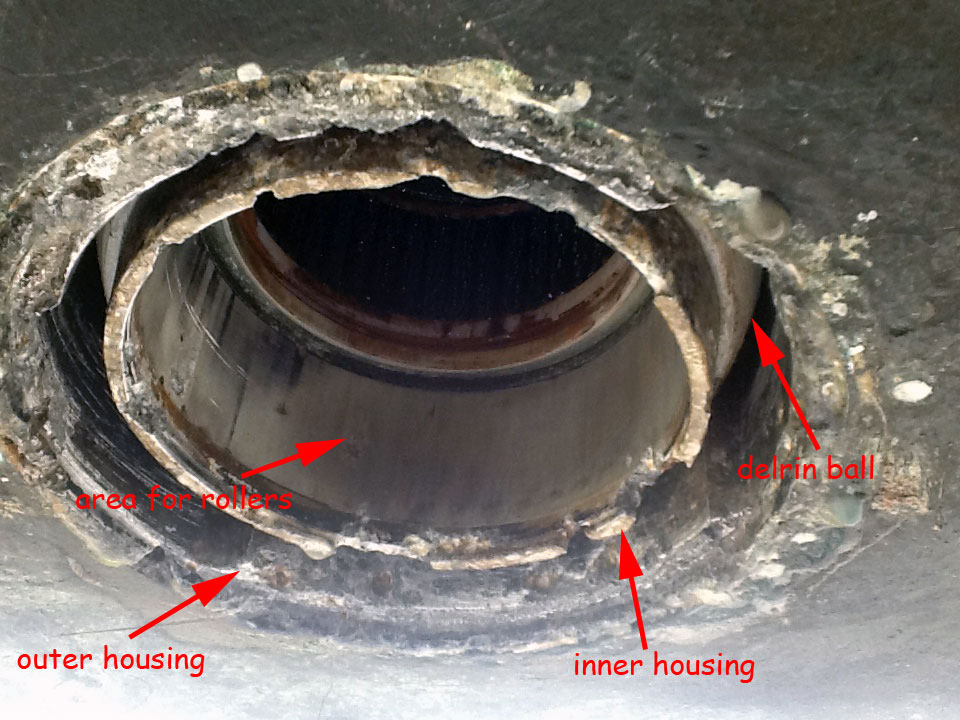
Test methods:
When the yacht is ashore, these connections can be tested by using an accurate resistance meter. One should connect one pole to the rudder shaft and the other pole to the propeller shaft or keel. The resistance should be infinite. If the resistance is less, one has a current leak and should test all above possible connections.
When the yacht is in the water, one can do the same test. A second test is to measure the voltage difference between the rudder and propeller shaft. Depending on the factors water type, temperature, used metals as described above, the voltage difference can vary from a couple of millivolts to tenths of volts. If a voltage difference is present, there will be no connection between the measured parts.
Electrolysis on aluminium and steel yachts:
The rules for avoiding electrolysis on aluminium and steel yachts are the same as on composite yachts: Disconnect the rudder from the rest of the ship. Mostly metal ships will have metal rudder blades. It’s advisable to protect these blades with a separate zinc anode on the rudder blade. Especially when different types of metals or metal mixture are used. For example a stainless steel rudderstock with a steel blade, or a aluminium rudder stock with an aluminium blade. The aluminium of the rudder stock is not the same as the aluminium of the blade. A small galvanic element is created that should be protected with an anode.
Electrolysis between the yacht and the outside world:
This type of electrolysis is the most feared type. A complete aluminium hull can dissolve in one month making the yacht a total loss. Instances are known even on composite yachts that lost a complete stainless steel rudder in one month time.
As this explanation of electrolysis is mainly based on protecting the rudder system, and as long as the rudder shaft is electrically disconnected from the rest of the yacht, the rudder shaft can’t suffer from electrolysis.
The only way to prevent electrolysis between your yacht and the outside world is to completely insolate the power supply via a galvanic isolator.
Following links provide more information on electrolysis and galvanic isolators.
http://www.yandina.com/electrolysis.htm
http://www.islandnet.com/robb/marine.html#CorrosionProtection
https://www.yachtsurvey.com/corrosion.htm
